Power Supply Development
Jul 12, 2013 @ 10:36pm
To power the raspberry pi, and sensitive sensors, I need a regulated power supply, but the larger devices like pump, servos, and valves all need a lot of power. The LiPo battery, while rated at 14.8V, can go above it. Wikipedia states that they get up to 4.23V/cell, so my 4 cell battery is 16.92V max. I was uncomfortable with most of the non-RC stuff seeing almost 17V when they were only rated at 12V (40% over spec), so I made a DCDC 17-10V->~12V Power supply, and a very large 5V power supply to power the servos (my searching gave me almost 2A as a spec value for them, and I want 3).
The only device I know is rated for the full RC battery voltage is the RC motor controller (though I'm not sure now, the rated voltage printed on it is for only 3S). I decided to connect that straight through to the battery, and to ease development allow plugging in a 12V AC adapter since it was in the range of expected LiPo battery voltages of 10.8-16.9V (2.7V/cell dead, 4.23V/cell full). I looked into relays and switches to give me a physical on/off switch and allow me to safely connect the RC battery and AC adapter at the same time. Turns out that the requirement that power flows through the board for the RC motor means that power switches need to be rated for 50A, and a 50A switch is expensive so I skipped that.
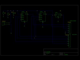
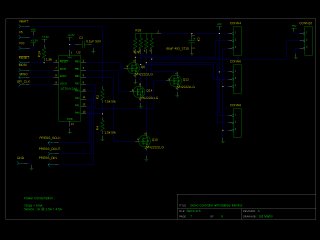
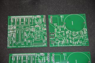
Design for the Power Supply (and the Raspberry Pi interface/IO board) was done entirely with gEDA tools, mostly gschem to make the schematics and pcb to produce the pcb. I didn't simulate anything as many of the chips weren't really something I could simulate with free software. I didn't test anything on a breadboard either as that would require I buy the chips, test them, and then try to use the same parts on the PCB. The circuits were simple enough that I thought it would be ok skipping the breadboard stage. As it turns out, I had a few problems, but nothing unfixable (yet)
12V Supply
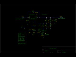
For the 12V supply section I went with just a linear regulator, the difference between the battery voltage and the 12V output was small. By getting a regulator with a very low dropout voltage and adjusting the output voltage with the raspberry pi I found I could keep the voltage drop across the regulator, and thus power dissipation, low enough. Loss of efficiency wasn't that big of a factor as the motor I selected is 500W+ or so, 5W of extra waste doesn't mean much for battery life.
Trying to find a linear regulator that could handle the 7-8A I needed also turned out to be difficult, so I ended up just making two independent 12V supplies, these two supplies are able to power the LEDs for the camera, the pump, and all valves.
This design lets the raspberry pi select one of 4 different output voltages for the 12V supply through the use of the VSel input lines, and the fault lines in the regulators allow the regulators to notify the raspberry pi when they drop out. This in turn lets the output voltage be kept as close as possible to the battery voltage, reducing power dissipation.
5V Supply
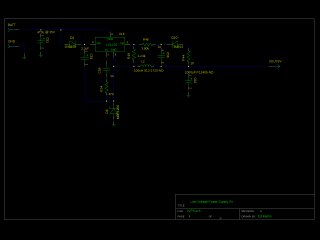
For the 5V supply I opted for a switching power supply, I was able to find a chip (LT1270A) which did everything I needed and had a circuit with most of the work done in the datasheet. It has a 100mA minimum current draw, but the raspberry pi draws more than that so it's not an issue (as long as the raspberry pi is connected), if you disconnect the raspberry pi the 5V turns into 15V or so. It would have been nice to put a circuit on there that kept it from ever going that high (a 6V Zener?), but I didn't do that.
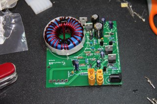
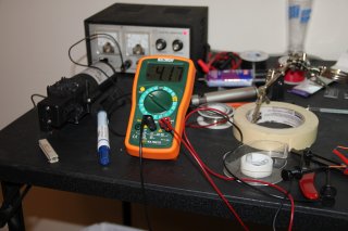
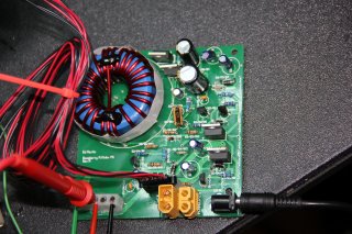
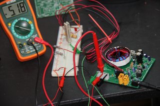
After construction of the power supply is quickly became apparent that the voltages were all wrong, after lots and lots of testing I found out that the problem was the schematic I copied out of the datasheet was copied incorrectly. The fix was to just move one leg of a capacitor and solder it to a nearby part. Here are the before (without power connector) and after (with power connector installed) images for that mod.
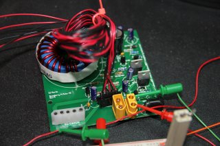
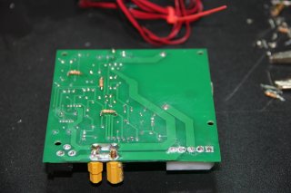
After doing this it was stable, but the voltage needed to be trimmed a bit by adding a resistor to the feedback network. Mods to the feedback networks were added to the bottom as seen below.
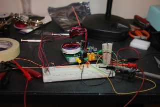
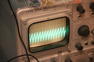
I did all the math and found heat sinks that should work, unfortunately after building everything I realized the heat sinks don't really have space, space is something that I absolutely need to take more care with when designing the PCB layouts. For testing everything in the power supply runs fine without a heat sink as shown below with a light load on the 5V supply.
