Raspberry Pi Interface Board Design
Jul 14, 2013 @ 9:08pm
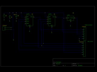
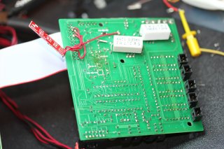
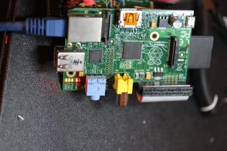
To control everything I am using the Raspberry Pi, running Raspbian. Everything I need that the Raspberry Pi needs to connect to I put on the interface board, and connect it to the Raspberry Pi through a ribbon cable. This connects both SPI and I2C to the interface board (as well as UART, which I will probably use for GPS). These interfaces are used for communication with the Raspberry Pi and the interface board has all the necessary electronics to power the sensors as well as the valves, pump and LEDs which need a large amount of power.
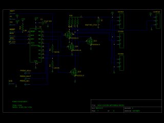
The valves, pump, and LEDs are controlled through I2C I/O expanders (MCP23017). The servos are controlled with the help of an AVR microprocessor connected through SPI, the AVR also interfaces with the depth detector (the depth detector is an absolute pressure sensor, however is has a wonky serial interface). The navigation sensors (compass, accelerometer, gyro) are on a SparkFun navigation board which connects through I2C. Additionally there is an I2C RTC clock (to hopefully provide more stable time then the raspberry pi can alone).
Valves, Pump, and LEDs
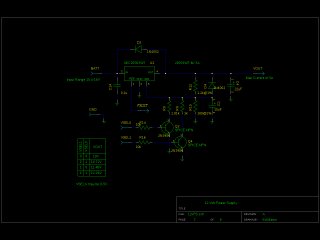
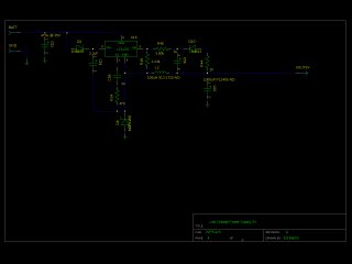
The Valves, Pump, and [camera lighting] LEDs are all simple devices but they all require well over an amp each of current at 12V. The valves needed the voltage reversed to switch between the open and closed positions. To do this the design I choose utilized many H-Bridges wired up to the I/O expanders (MCP23017) to power the valves. The LEDs and pump were then wired up to FETs to power those devices. The extra pins on the I/O expanders were routed out to use as sensors for flooding, to control the 12V power supply output voltage, and to read it's fault flags.
Servos and AVR
I thought about controlling the servos by bitbanging the hobby servo signals, but that's not something I felt comfortable doing on the Raspberry Pi, Linux isn't a real time OS (though it can be pretty good), and trying to make something run every 5-10ms or so with ~50μs accuracy seemed difficult. A small microprocessor was better suited for that. It was a similar story with the pressure sensor I selected, the protocol switches from srychnous serial communication to asrychnrous interrupts depending on what you do, again, that seemed difficult with the raspberry pi, and it was better to do with microprocessor. I selected the ATtiny24A do all of this, it can be programmed over the SPI data pins, and when running can communicate over the SPI pins to the Raspberry Pi.
IMU Sensors
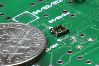
To actually navigate underwater without external sensors (I can't use GPS) the submarine needs an inertial measuring unit (IMU). At an absolute minimum a 3-axis gyro and a 3-axis accelerometer is required. Additionally other external sensors (and even commands) can be used when calculating your position, a pressure sensor can help very significantly with calculating the depth and vertical velocity, a compass can help by giving you a heading. I originally intended to solder on all of these sensors onto the interface board. Unfortunately it turned out to be very difficult to solder 16-LGA chips, even with a temperature controlled hot air gun, a solder mask, and solder paste, I couldn't get any of the chips soldered onto the board. The compass is shown below with a dime for scale (and the huge solder mess I made trying to get it on there).
Eventually I gave up, bought what was essentially the same chips, but soldered onto a small board from SparkFun. That board was easy enough to connect up to the interface board (only 4 wires). It unfortunately lacks the interrupt outputs that my original design has, but I don't think that is going to be a problem.
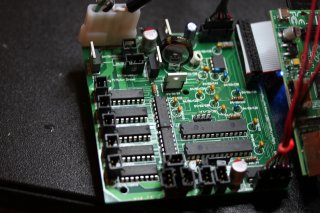
Here are the pictures during testing (now), the red board hanging off the bottom is the IMU board.
